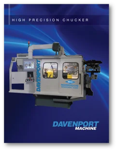
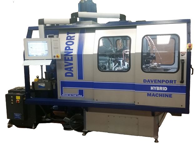
The Davenport five-spindle chucking machine is designed for medium- and high-volume secondary operation work on parts up to 2 1/4” diameter.
Significantly progressive in its adaptability to specific jobs, the Chucker version of the Davenport machine is used for secondary operations.
Optimum machining flexibility is provided through 9 tooling positions, while common operations such as; cross drill, cross tap, thread roll, mill, and slot can be complete using standard Davenport attachments.
Index time is as little as 0.4 seconds. Quick index & cycle time teamed with unparalleled machining…has allowed Davenport to be the most economical chucking machine available today.
Most tooling and attachments used on the Davenport Model B Bar Machine can also be used on the Chucker.
What Makes the High Precision Chucker Innovative?
Davenport Machine & (MIC) teamed up to develop of the High Precision Chucker, utilizing innovations from MIC along with elements from Davenport High Precision Head, providing precision and durability.
- Aerospace
- Automotive
- Defense
- and much more...

Get Access to the Brochure
New Machine |
|---|
Oversize or Regular Capacity
|
Cycle Index 75, 60, or 45 Cycle |
Threading attachment option |
10 Hp Main Drive Motor |
Electrics (Please specify voltage required) |
Motorized Bijur System |
Center Drive with Standard Gear |
Double Action Chip Conveyor |
1st and 2nd Position Tool Posts and Cross Slides |
3rd Position Cross Slide Option |
Optional 3rd Position Cross Slide Available at Additional Cost |
Loading & Ejecting Options |
Sound enclosure with interlocking doors |
Considering a remanufacture? Chucker remanufacture includes: |
Stationary Head |
Revolving Head |
Inner and Outer Revolving Spindles with Bronze Bearings |
Ring Gear |
Barrel Chucking on Work Spindles, Burring Spindles, High-speed Clutch, and Starting Clutch |
1st and 2nd Position Cross Slides using CJWinter 132 EG Reversible Slides |
Stationary Tool Spindles and Boxes |
Main Bearings and Bushings |
Lubrication System with Motorized Pump |
Capacity | |
|---|---|
Regular capacity of feed tubes | 9/16″ round, 1/2″ hexagon and 3/8″ square. Special feed tubes with feed fingers soldered in can be furnished to take a stock up to 5/8″ round, 9/16″ hexagon and 7/16″ square |
Longest length fed | 3″ |
Longest length turned | 2 1/2″ |
Number of changes of spindle speeds | 27 |
Range of spindle speeds | 500 – 4,500 RPM |
Number of changes of feeds | 60 |
Speeds | |
Driving shaft | 1,500 RPM |
Hand wheel shaft | 750 RPM |
Indexing head, feeding stock, etc. | 4/10 second constant When cutting steel the threading spindle revolves in the same direction as the work spindle at a ratio of 3 to 4 while threading tool is running to work and 3 to 2 while running off. When threading on brass work the threading spindle is stopped when tool is running on but revolves twice the speed of the work spindle to run off. |
First feed change gear shaft | 200 |
Ratio of worm and wheel | 60 to 6 |
Size of Equipment | |
Diameter of circular tools | 2″ |
Diameter of hole in tool spindle | 3/4″ |
Outside diameter of tool spindle | 1 3/8″ |
Least distance between chuck and tool spindle | 2 1/8″ |
Greatest distance between chuck and tool spindle | 4 13/16″ |
Diameter of long feed cams | 7 1/2″ |
Diameter of cross feed cams | 6″ |
Thickness of cams | 3/8″ |
Equipment | |
Cams | 9 |
Spindle change gears | 2 |
Feed change gears | 1 |
Threading gears | 2 |
Set of wrenches and screwdrivers | 1 |
Motor Drive | |
Machine designed for motor drive 10 H.P., 1,800 RPM. Motor and all electrical controls are extra. | |
Floor Space
| |
39″ x 61″. Distance from top spindle to floor is 44 1/2″. | |
Dimensions and Weight | |
Size crate | 60″ W x 112″ L x 96″ H |
Net weight | 3,600 lbs (domestic or foreign) |
Gross weight | 3,800 lbs (domestic / crated) 4,000 lbs (foreign / boxed) |
Color | |
Machine Tool Builders Association Standard Gray | |
A Profile of Productivity
Learn about the various types of stems, valves, shafts and races that are produced efficiently on the Chucker.
Recent Related Articles

What’s New at Davenport Machine?


