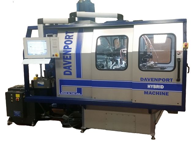
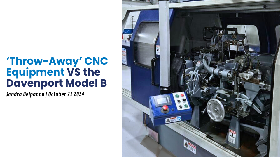
Multi-spindle screw machines provide superior productivity over traditional single-spindle screw machines and lathes. In a multi-spindle machine, each spindle has two opposing tools cutting in the work zone, allowing for multiple operations to be done at once. Parts can be machined in faster cycle times than other multi-spindle machines. A complete part is produced with every index of the revolving head.
The Davenport Model B has the fastest production and index speeds on the market. Davenport has an expansive catalogue of attachments, providing solutions for a variety of small part applications.
Since 1900, The Model B continues to be the most economical, fastest multi-spindle screw machine available.
The Model B includes:
- Threading capability
- 5th position burring attachment
- Countersink attachment
- Chip conveyor
- Stock carrier with cover
- Stock depletion sensor
- Sound enclosure
Model B Davenport Machine Operations
Our multi-spindle automatic screw machines allow the use of up to four revolving stationary spindles.
- Slot
- Burr
- Broach
- Form
- Ream
- Thread Roll
- Tap
- Skive
- Drill
Model B Benefits:
- Proven Reliability
- Enduring Technology
- Flexibility
- Fast Parts Production
- Small Footprint
- Dedicated Factory Support
Working with Davenport
New Model B | Model B Remanufacture |
|---|---|
Oversize or Regular Capacity | 5th Position Stationary Head Burring Attachment |
Cycle Index 75, 60, or 45 Cycle | Stationary Head |
Threading Attachment Option | Revolving Head |
5th Position Stationary Head Burring Attachment | Inner and Outer Work Spindles |
5th Position Countersink Attachment | Ball Bearing Feed Tube Assemblies |
10 Hp Main Drive Motor | Chuck Slides |
Electrics (Please specify voltage required) | Barrel Chucking |
Motorized Bijur System | 1st and 2nd Position CJWinter Cross Slides |
Barrel Chucking | Stationary Tool Spindles and Boxes |
Center Drive with Standard Gear | Bearings and Bushings |
Double Action Chip Conveyor | Motorized Lube System |
1st and 2nd Position Tool Posts and Cross Slides | |
3rd & 5th Position Swing Arms | |
Stock Depletion Sensor | |
DeClutch & Brake Mechanism | |
Stock Carrier & Cover for 12 Foot Long Bar | |
Sound Enclosure with Interlocking Doors | |
Capacity | ||
|---|---|---|
Regular capacity of feed tubes | 9/16″ round, 1/2″ hexagon and 3/8″ square. Special feed tubes with feed fingers soldered in can be furnished to take a stock up to 5/8″ round, 9/16″ hexagon and 7/16″ square | |
Longest length fed | 3″ | |
Longest length turned | 2 1/2″ | |
Number of changes of spindle speeds | 27 | |
Range of spindle speeds | 500 – 4,500 RPM | |
Number of changes of feeds | 60 | |
Range of feed gears | .8 – 18.4 seconds | |
Speeds | ||
Driving shaft | 1,500 RPM | |
Hand wheel shaft | 750 RPM | |
Indexing head, feeding stock, etc. | 4/10 second constant When cutting steel the threading spindle revolves in the same direction as the work spindle at a ratio of 3 to 4 while threading tool is running to work and 3 to 2 while running off. When threading on brass work the threading spindle is stopped when tool is running on but revolves twice the speed of the work spindle to run off. | |
First feed change gear shaft | 200 | |
Ratio of worm and wheel | 60 to 6 | |
Size of Equipment | ||
Diameter of circular tools | 2″ | |
Diameter of hole in tool spindle | 3/4″ | |
Outside diameter of tool spindle | 1 3/8″ | |
Least distance between chuck and tool spindle | 2 1/8″ | |
Greatest distance between chuck and tool spindle | 4 13/16″ | |
Diameter of long feed cams | 7 1/2″ | |
Diameter of cross feed cams | 6″ | |
Thickness of cams | 3/8″ | |
Equipment | ||
Chucks and feed fingers | 5 each | |
Cams | 9 | |
Spindle change gears | 2 | |
Feed change gears | 1 | |
Threading gears | 2 | |
Set of wrenches and screwdrivers | 1 | |
Motor Drive | ||
Machine designed for motor drive 10 H.P., 1,800 RPM. Motor and all electrical controls are extra. | ||
Floor Space | ||
39″ x 61″. Distance from top spindle to floor is 44 1/2″. | ||
Model B – Oversize | ||
Same equipment as above but with oversize spindles and feed tubes to take the stock up to 13/16″ round, 11/16″ hexagon and 9/16″ square. Special one piece feed tube and feed finger can be furnished to take stock up to 7/8″ round, 3/4″ hexagon and 19/32″ square. | ||
Dimensions and Weight | ||
Machine | Wire Case Carrier | |
Size crate | 60″ W x 112″ L x 96″ H | 124″ x 12″ x 12″ |
Net weight | 3,600 lbs (domestic or foreign) | 175 lbs (domestic or foreign) |
Gross weight | 3,800 lbs (domestic / crated) 4,000 lbs (foreign / boxed) | 225 lbs (domestic / crated) 225 lbs (foreign / boxed) |
Color | ||
Machine Tool Builders Association Standard Gray | ||
Davenport’s World of Attachments
A vast array of precision attachments offers more flexibility. Learn why the Model B gets the job done smoother, faster and more profitable.
Recent Related Articles
How OEM Certified Remanufacture Makes Your Model-B Better Than New
What are the Top 3 Benefits of a Davenport Machine OEM Rebuild?

What’s New at Davenport Machine?
